Figuring out an algorithm to place models on irregular surfaces

tl;dr: Skip to My consideration and My questions.

The goal

I want to write a function that lets me place models on surfaces. The model is placed at a given location with an orientation that aligns with both the orientation of the surface, and the direction that the player (who is placing the model) is facing.

However, a location for a model may be rejected if:

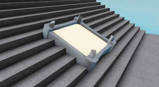
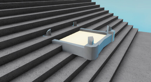
  1. Part of the model clips into the ground or a wall.
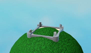
  2. Part of the model reaches over a cliff.
  3. The slope of the surface is too steep.

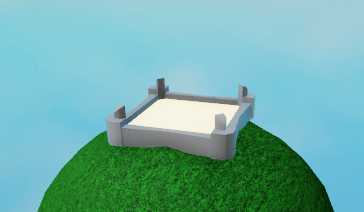
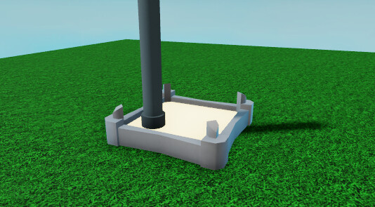
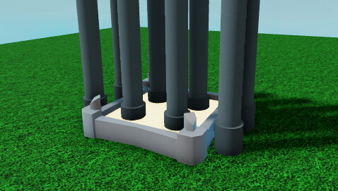
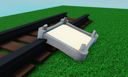
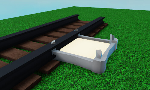
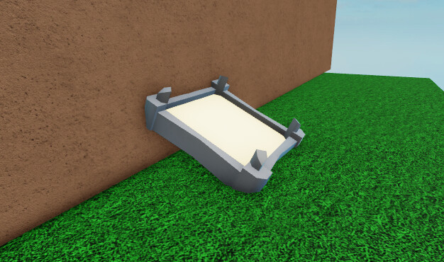
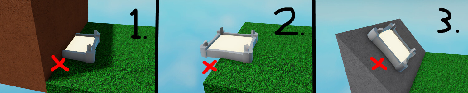
So the following 3 examples should all be rejected:

The situation

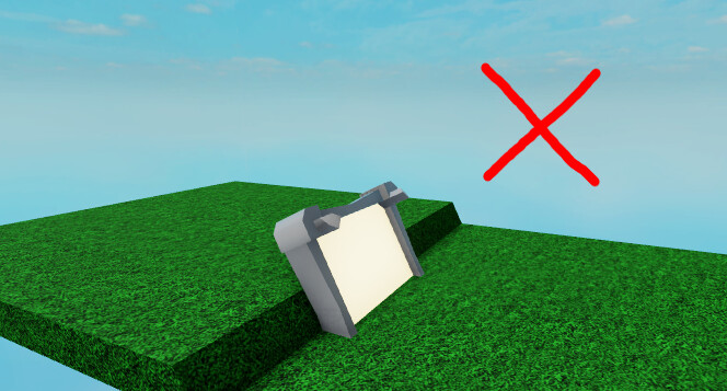
The space in which models may be placed contains many surfaces with irregular elevations and orientations. Below is an example of what an irregular surface may look like:

The elevation between the left and right half of this surface differs not too much, but there is a small but very very steep slope right in the middle of it. If I were to place a model that aligns with the surface’s normal right in the middle of that surface, it will be rejected as per condition 1. (Part of the model clips into the ground or a wall)

image

Unfortunately, the space in which models may be placed has many of those locations where a naïve algorithm that aligns a model with the surface’s normal, would lead to rejection. This happens, for example, through little rocks on the surface or stairs that would cause the model to clip into its steps. So using a naïve algorithm that aligns a model with the surface’s normal would lead to bad user experience.

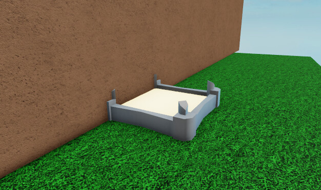
However, a smarter algorithm might detect that the area surrounding the model is on average flat enough to place the model in such a way that it passes all 3 conditions:

image

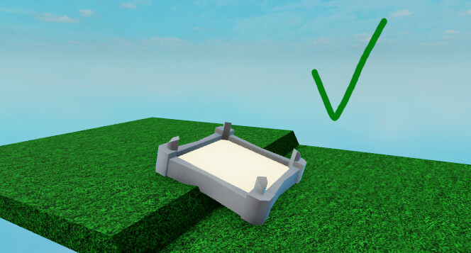
In this example, the model does not clip into the ground or a wall. It does not reach over a cliff, and it also does not rest on a steep slope. This is the kind of algorithm I would like to write.

My consideration

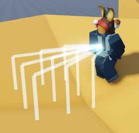
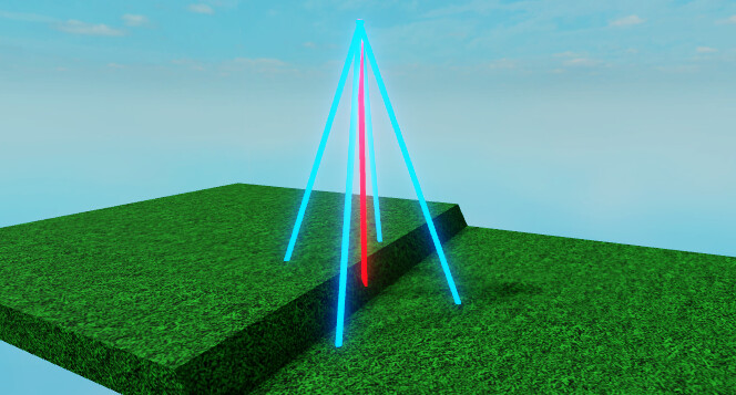
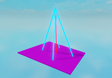
  1. First I would need to find the location for the model and check if there is enough space. I could do this by casting a ray down vertically (for the location) and 4 other rays diagonally to check if it does not hit a surface too far up or down. Visual representation:

image

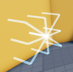
  1. If all rays have hit a BasePart, I would construct a new (virtual) plane to place the model on using the 5 positions returned by the 5 rays. Visual representation:

image

  1. Finally, I would check if the slope of this virtual surface is not too steep, and then I would align the model on this virtual surface such that it faces the same direction as the player.

Unfortunately this algorithm does have its flaws. For example, if one of the rays in step 1 returns a location that is only slightly higher up than the others, there is no good way of knowing if this means that the ray hit a wall, or if the surface is slanted. You could check the direction of the returned normal as well, but then you run into the problem where models may not be placed on e.g. stairs, because the algorithm treats the side of a step as a wall.

My questions

That all being said, I have a couple of questions:

a. Is this a smart way of tackling the problem, or is there a better approach that I am missing?

b. If this approach is fine, how would I execute the second and third step of my algorithm? (Constructing a plane using the 5 given locations, and aligning the model on this surface, facing the same direction of a player)

1 Like

Personally, I would check there is enough space as the final step. As a first step, I would determine the plane that the model should be placed on.

Before going into more detail though, it would help to have some more examples of cases that would be accepted and rejected. I’m especially interested in cases where there might be a small part which would intersect with the model.

As requested, I’ve made some extra pictures illustrating some edge cases and the desired results. Note that for some cases multiple outputs would be fine, though I do have my preferences of course.


Case 1: Hill tops

This is a situation where the location at which a model is placed is higher up than the locations to the left, right, front and back, but the slopes in all 4 directions are not steep enough for rejection.

Desired output: The model is placed upright at the highest point.

image

Incorrect output: The sides are aligned, but the middle part is clipping through the hill top. This would violate condition 1. (clipping through the ground)

image


Case 2: Stairs

This is a situation where looking from above, all surfaces are horizontal, but looking from the side there are many ‘low’ walls.

Desired output: The model is aligned with the stairs as if the stairs were covered with giant cardboard sheets, provided that its angle does not exceed a threshold (condition 3 from the original post)

image

Incorrect output: The model is aligned with an individual step, on one side it clips into other steps, and on the other side it hovers over other steps. This violates condition 1.

image


Case 3: Thin yet tall props

This is a situation where the model is placed nearby props that are thin and tall.

Desired output: The model’s location is rejected.

Alternative, though undesired output: The model may clip through the prop as long as the prop is not obstructing too much of the model (you can still see more than ~75% of the model)

image

Incorrect output: When there are many props clipping through the model, the model’s location should be rejected.

image


Case 4: Low props

This is a situation where a model is placed near props that are very low to the ground. The prop shown in the examples would be the tallest prop I would still consider a ‘low prop’.

Desired output: The model should be placed such that it looks as if it were ‘dropped’ onto the props, provided that its angle does not exceed a threshold (condition 3 from the original post)

image

Alternative output: The model may clip slightly into the low prop.

image


Case 5: Walls

This is a situation where a model is placed near a tall vertical surface.

Desired output: If the model intersects the wall, its location should be rejected.

Alternative, though undesired output: The model is slightly slanted diagonally against the wall.

image

Incorrect output: The model intersects with the wall.

image


I understand that it would be (near) impossible to write an algorithm that correctly deals with all these edge cases, but this should at least provide some more insight, and any approach that comes even close to dealing with these edge cases would be amazing.

Hey :wave:

I can’t come up with a simple algorithm to solve all these edge cases, and I don’t think there really is something simple and neat that can be explained in a few sentences.

Instead, I’ll share some kind of method I use when I encounter problems like that. Here, the complexity comes from the multiple edge cases you presented. Each of them alone are not really “hard”, there is just a lot of stuff to think of when you are trying to solve the whole thing at once.

Approach

I haven’t invented this, it’s just a way to apply tests driven development (commonly known as TDD) in practice. This won’t be some hardcore TDD with tiny unit tests and too much mocks: I’ll talk more about integration level tests because unit tests are more bound to the implementation. Since we don’t know what the implementation will be, we need to write tests on the general solution.

Setup

First step, you need to come up with a way to run automated tests on your solution. Good thing: there is an open source test framework by Roblox called TestEZ (pronounced test-easy). If you didn’t know about it, you should get familiar with it because it is really helpful whenever you want to make sure something actually works (which I guess is always?).

Github: GitHub - Roblox/testez: BDD-style test and assertion library for Roblox Lua
Documentation site: TestEZ Documentation

You can setup TestEZ to run when you press “Play” in Studio or with something like run-in-roblox. Pick something that goes with your workflow, does not really matter as long as it’s really easy and doesn’t take much time.

Since your problem placing instances on other instances, I suggest to create different groups of instances to test the solution. Take the different parts from the situations you described and bundle them together. Each bundle should include the place where you expect the object to be placed and the input (which would be where the player is). These will be useful for building up your test cases.

Development

Now that you have the workflow setup, it’s time to actually code the solution.

  1. Create a test case
    Yep. You start to code with a test. Yep, it will fail because you didn’t implement the behavior in the solution yet. That’s ok and it’s an important step. When a test fails, it means that the test is actually verifying something.

  2. Code your solution so that the new test case passes
    Now you can go implement the solution. Make sure to run the tests often, because you don’t want to lose previous existing functionality covered by tests.

  3. Refactor the code if necessary
    It’s important to take a moment to see if you can improve the quality of the code. If you ever mess up your refactor, the test should start failing again and you’ll be aware of the regression (so you can find the bug). Your solution will keep growing, so it’s best to keep the code clean.

  4. Repeat step 1 to 3 until your solution does what it needs to do :slight_smile:

About Unit Tests

Now that we’ve described how to incrementally add complexity by adding new test cases, I wanted to circle back on unit tests and when they are useful.

As the general solution increase in complexity, you’ll create new functions or classes within the general solution to solve a smaller part of the problem (i.e. getting a plane data from some points, finding if props are within a certain region, etc). All these tinier problem-solvers are the building blocks of the global solution: you need to make sure they’re reliable. That’s where you should write unit tests to have that guarantee.

That means that within step #2 from above, you can create an inner loop with step 1 to 3, but on a smaller level, for a specific function you’d use within the general solution.

Summary

For some new comers, developing tests along with code sometimes seems like an additional (or even unnecessary) task. Some kind of tests are harder to write than others, but when it comes to a specific algorithm like you describe, they’re generally really easy. You just need to pass some input to a function, and then asserts that the result is what you expect from it.

There is a bunch of benefits that comes with this development practice. One is that, you often end up naturally with at least “ok” or even “good” quality code when doing testing, because you’ll tend to split up behavior into functions or classes, so that they are easier to tests. If your tests are neat and simple, it probably means that the implementation is not bad.

If it’s the first time you ever write tests, don’t feel discouraged if you find it hard or if you feel like you always need to go change them. After all, writing good tests is a skill like anything else, it takes practice to get really good at it. So making simple tests that persist through time and variation of the implementation is not something you achieve in one day.

I hope this helps you out getting though the door and start coding a solution for your problem! If you (or anyone interested) has any question, feel free to reply or ping me on discord. I’m always happy to help out :grin:

3 Likes

I have revisited this problem and found a better approach to placing structures.

The idea

My new approach casts 9 rays down in a 3x3 grid. But before that, it casts 9 rays forward from a center point towards the starting point of the 9 rays going downwards, essentially creating the following visualization.

image

If any of the rays forward hit an object, it is considered a ‘wall’ that is hit. If that happens, the process will instead cast 9 rays forward, once again with 9 additional raycasts prior being cast from a center point towards the starting point of those 9 rays, creating this alternative visualization.

image

The 9 raycasts towards the ground or wall all have a limited range and need to hit some BasePart to verify that the ground or wall does not suddenly stop (which is done to detect cliffs). The other 9 raycasts connecting the center point and the 9 parallel raycasts should not hit anything, to verify that there is no obstacles blocking the ground or wall.

If all 9 raycasts going downwards or forward hit a ground or wall, the algorithm considers it a potential place for a model. It will then run another algorithm to construct a ‘best fitting’ plane from the 9 points where the rays hit an object. This plane is then used to find the average slope of the (potentially irregular) surface it is being placed on. And the slope of this new surface is checked against to make sure it is not too steep.

Finally, the model is placed at the location where the center-most ray hit an object, and it is rotated such that it angles with the slope of the best fitting plane that was constructed.

Performance

Given that all 9 parallel raycasts towards the ground need to hit an object, the new approach will make sure no models can be placed on the edge of a cliff. And the other 9 raycasts are used to verify if there are no obstacles in the way, to ensure no model can be placed such that it ‘clips into’ a wall or other objects.

Using a ‘best fitting’ plane approach will also help smooth out any potential irregularities of the surface is it being place on. So when placed on top of a hill, the model should still point upwards.

Limitations

  1. For bigger models, 9 raycasts might be too few as the distance between the raycasts becomes large and the algorithm may fail to detect holes in the ground.

  2. There are some edge cases in which the center-most raycast falls in a small pit or on top of a thin object. The surrounding raycasts may then hit other BaseParts located higher up or further down. This will create a situation where the ‘height’ at which the model is placed does not match the actual height of the surface onto which the raycasts were aimed, so the model might be placed on top of a lantern pole or in a crack in the floor. I am still trying to figure out a method that will be able to detect these situations, but one option might be to check the height of the plane’s center point against the height of where the center-most ray hit a BasePart, then pick the position with the greatest Y value. This can help mitigate situations where an object is placed into a pit, but it will not solve situations where the model is placed on top of spiky surfaces.

5 Likes